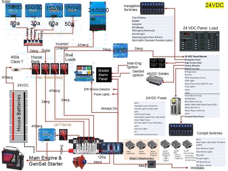
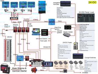
DC Power System
The Refit plan is as follows:
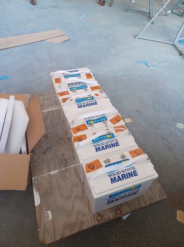
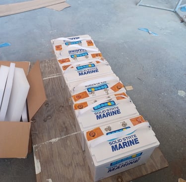
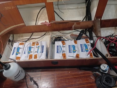
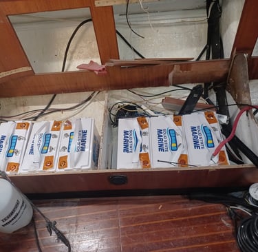
Lithium - www.solidstatemarine.com - 24 VDC, 900ah total capacity
Solar Power - TBD - aiming for a combination of Bifacial PERC and CIGS panels for 4+KW. www.bougerv.com
Lights - Upgrade all to 24VDC LEDs
Pumps - Everything replaced with 24VDC
Inverter - 24V/5000W
18 Apr 2025 - The detailed design is basically done to the point where the major components are now on order. Rogan at Cay Electronics was instrumental to helping me refine and finalize this design.
The DC Power system is the heart of the boat.
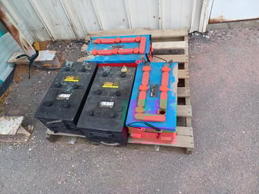
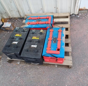
We store power using Solid State Lithium batteries setup in a 24VDC. We want to have sufficient storage to operate everything for 5 days without significant solar input and without resorting to using the GenSet. For now we are looking for a combination of batteries to get us to 900AH at 24VDC.
We can generate DC Power via Solar Panels (Direct DC) and via converted AC power through a Inverter/Charger.
DC power consumers on the boat:
Starter Batteries for the Main Engine and GenSet
Supplement for the Windlass
Sailing and Navigation Electronics
IT Infrastructure (DC to DC step down transformers) to include USB chargers
Lighting (interior, exterior, navigation)
Galley Refrigeration
Fresh and Saltwater Pumps
Electric Winches (via a 48VDC converter)

DC Electrical System Design and Explanation
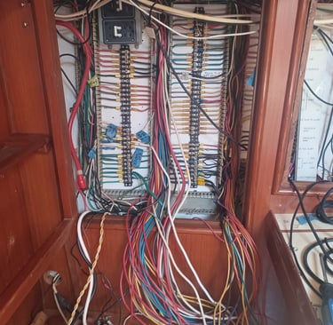
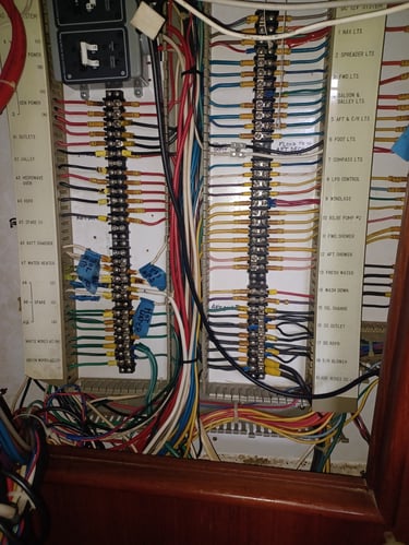
We have chosen to completely update the DC system on the boat. We inherited a boat built on a 12VDC electrical system. The lighting was still incandescent, and the inverter onboard was just enough to run a navigation laptop dating back to the 2000's. The batteries consisted of 4 Group 8D lead acid batteries that hadn't been properly maintained in years. In fact one was home to part of the termite nest on the boat.
So before going on, I'd like to talk about some lessons we learned from building the 12VDC system on the Beneteau.
12VDC is very subject to voltage drop especially in longer and undersized wire runs.
12VDC requires very large gaged wiring (cabling) due to item #1.
The Gel Lithium batteries don't like being jolted - 2 of the 6 original batteries have ruptured gel packs rending the batteries unfit for use. Due to the electrical characteristics of different groups of batteries, you can not simply replace batteries that fail in a parallel bank. If batteries fail, their replacements must go into a separate bank which will complicate your wiring system significantly.
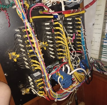
The Beneteau's wiring harness was never designed for the amount of electrical and electronics we put on it necessitating adding new wires in many areas to compensate.
Corrosion is a thing - when we uninstalled stuff on the old boat, we noted lots of corrosion in areas we thought were sealed.
The crimpon connectors continued to be an issue
The Balmar Alternator worked well once we made the decision to treat the main engine as either a generator or as propulsion. It didn't like to run both the electrical load and propel the boat at the same time. Also we saw the balmar energize and then drop as the house bank topped up to 100% - it was cycling between 99% and 100% for no good reason. We eventually put the regulator power from the ignition through a basic switch that allowed us to control when the alternator was energized to produce power. We only powered it when we actually wanted to produce power.
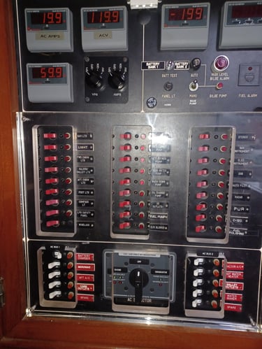
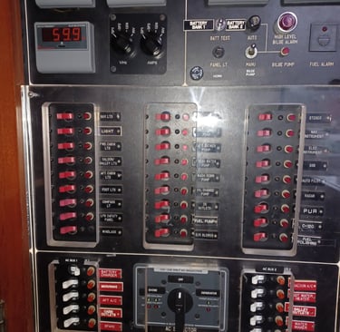
In order to keep the size of the main power panel down given all of the extra power consumers on the boat, we installed external fuse blocks and switch panels. We were able to feed these with new dedicated heavier gauge wire, will still giving us control of the devices. We were very happy with how this worked.
So this translated to some new requirements and background for how the new system is designed.
24VDC for the boat. The Hylas was wired with much heavier gage wire (3.5 mm - 10 AWG - from the factory and by moving the loads to 24VDC, we anticipate our power environment will be much more stable
We are going to use dielectric grease on all connectors to try to lesson corrosion and then use the crimper from the Ferrule set on all terminal connectors to try to get better crimps and try to limit corrosion. We are also going to use a newish process where the connector is sealed in melted plastic for any connection that might every see water.
We are going to use Solid State Lithium batteries. These are fairly new in the market, but they are being touted as bullet proof. They are more expensive, but if their failure rate is lower, it will be worth it.
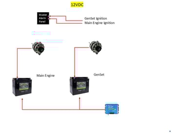
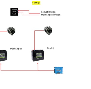
We have decided to include another High Output Alternator in the design from the start as a redundant source of alternative power if the GenSet fails. We will wire it up the same as the Beneteau with the regulator unpowered unless we actually want to produce power.
We are going to install the new main engine as 24VDC to keep wiring consistent but the starter battery is going to be traditional. The extra cost of lithium is not justified due to the fact that it still must be isolated from the main bank due to likely electrical imbalances causing sudden and very large transfers of power when combined with the house bank, so additional DC-DC chargers are required to safely operate it in the environment.
We have chosen to leave the GenSet as 12VDC. It is already very isolated electrically and leaving it 12VDC will actually simplify the overall design - it's Alternator is just for it's battery. We might add a 24-12 VDC trickle charger to keep it up, but we anticipate running the GenSet at least weekly to keep the diesel part of it happier.
We will likely only bring a single Shore Power input in as opposed to the 2 installed currently. We will likely abandon the 2nd line in place in case we decide to change it up in the future
We have discovered that we can reuse most of the light fixtures by installing new 24VDC capable LED light bulbs. There are a handful of fluorescent fixtures that we will replace with 24VDC LEDs
We have also found that most of the electronics are 24VDC capable. Notable exceptions are the Fusion stereo, the VHF radios and the NMEA2000 backbone and associated devices. We will install device specific step down buck transformers at the device to deal with 12VDC devices.
We have also decided to upgrade the windlass to 24VDC. The windlass is 35 years old and we honestly don't know what kind of shape it is really in. We also have a seal rebuild kit for it. With a 24VDC motor, it should have plenty of juice to deal with the chain and a heavier anchor.
The refrigeration devices are all natively capable of 24VDC so they will likely run better with lower voltage line losses.
We will use a fuse block to power most of the lights, usb and fan loads throughout the boat since they all have local switches. This will keep the number switches in the main panel down and reserved for the more critical devices.
Solar is an interesting discussion with the advent of different panel technologies. The MPPT controllers are sized based on the tentative plan for the panels - more on this later.
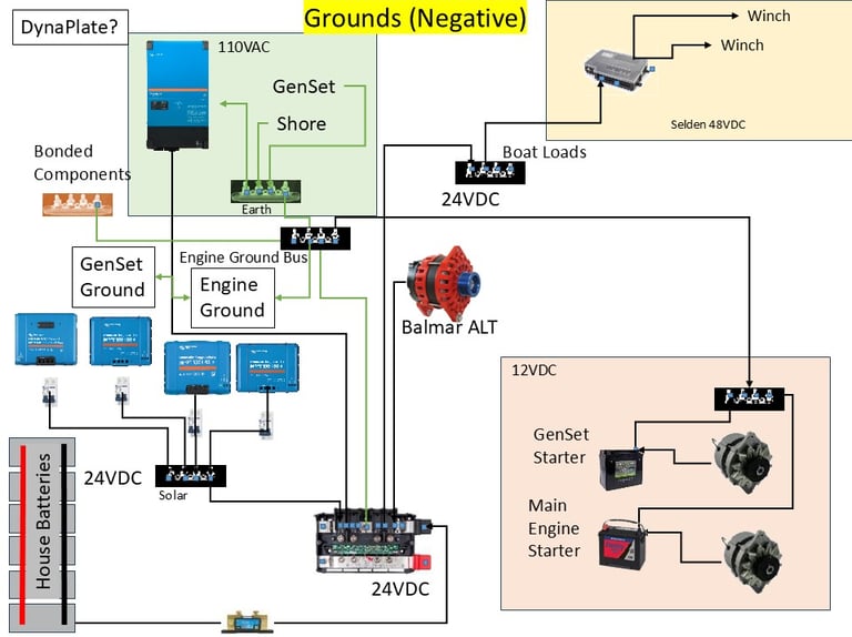
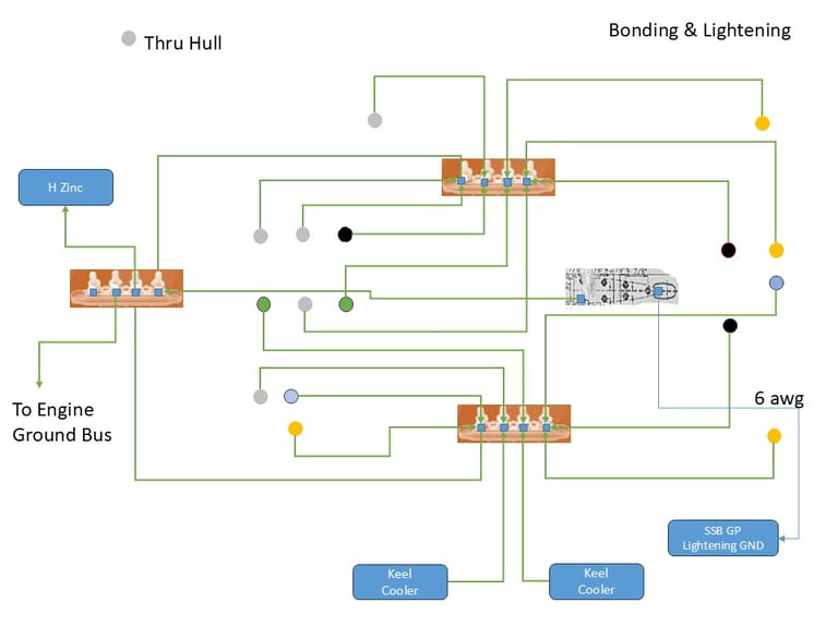
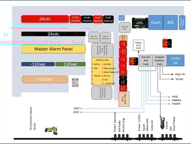
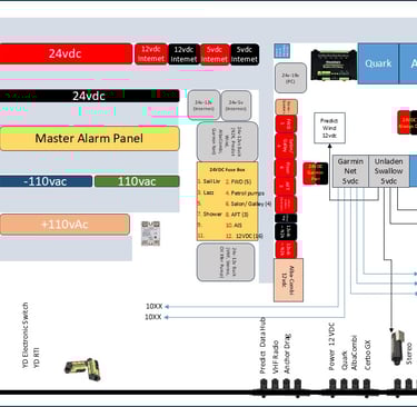
We are also going to be very direct on the bonding system for the boat. There were issues with broken wires and significant galvanic corrosion issues on the boat at purchase time. We are going to make sure we get this right out of the gate. The diagram above shows the plan for the bonding system.
Ground on a boat is often misunderstood and I will admit I didn't have a great grasp of it either. I have to give Rogan at Cay Electronics (my consultant on this project) for finally explaining it in understandable and actionable terms.
Each "part" of the electrical system (12, 24, 110, bonding) should be handled on its own dedicated bus.
Each of those buses are then tied (with a single dedicated conductor) to a central master grounding bus - this includes the engine block ground
There is a single conductor from the master grounding bus tied to the negative terminal on the house battery bus.
This provides a single path for each item to reach back to the batteries preventing ground loops which could lead to stray current.
If we were planning to use shore power on a regular basis we would need a ground isolation transformer, but we expect our onboard power generation to be sufficient for our needs
There is a picture depicting the bonding (and lightening grounding) plan and then a second diagram showing all of the grounding buses and how they relate to one another.
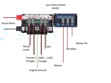
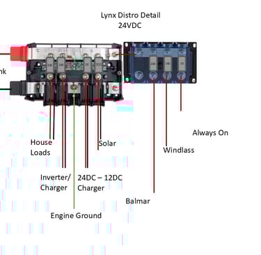
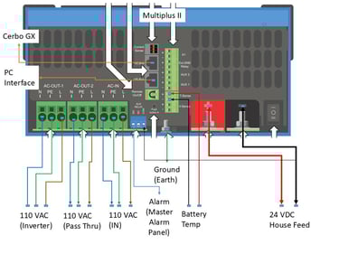
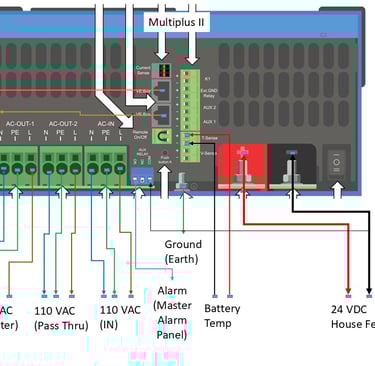
On the Beneteau, the Cerbo GX was powered from the Lynx BMS. This provided power essentially directly from the house bank. The new batteries have internal BMSs so we need to power it from the Lynx Distro bus to ensure there is always power it the house bank is connected. We also figured that the Master Alarm panel was part of our monitoring system, it should be similarly powered.
We will cover the Master Alarm panel and the Cerbo GX design in different write-ups.
Important Disclaimer - I am not a certified marine electrician. The below was developed with the paid help of several folks who do this for a living. Unless you are actually trained to do this type of design, attempting on your own could result in serious injury or death. The voltages coming through the Solar Controllers will kill you. The amount of power stored in the batteries will easily weld steel if short circuited. Please seek qualified help before designing something like this and if you are unsure of how to install, the university of you tube is full of advice that can kill you or leave you with an unsafe system.
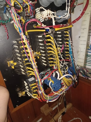
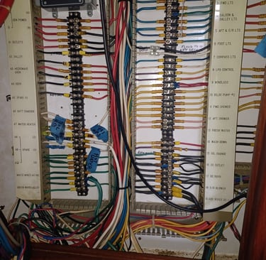
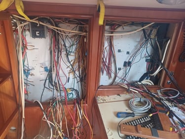
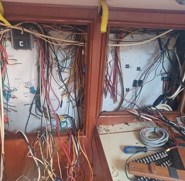
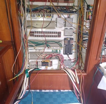
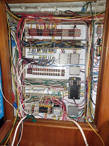
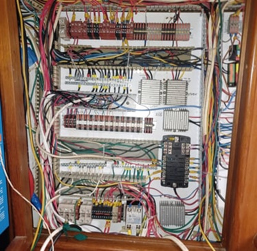
Electrical system disassembly - 8 may
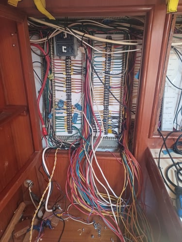
Patch Panel bay layout planning - 11 and implementation 13 May


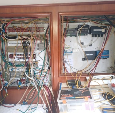
Patch Panel bay layout planning - 14
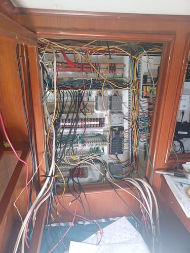
- The original factory wiring is mostly hooked back up except for the lights and 12 V sockets - they are all too short for their intended homes
15 May Update
The factory harness is done on the DC side except for the grounds
I need to do the AC side first due to reusing the color Black - I want to make sure that all of the HOT AC lines are accounted for before committing the remaining blacks to the DC Ground Bus Bar.
Still need to trace the non-factory wiring.
The bundle on the right side of the picture is related to the mast wiring harness. There is a terminal block mounted under the forward salon seat where this harness terminates. Based on that fact, we can move forward with another terminal block mounted against the forward bulkhead in this electronics bay that will then feed the navigation switch panel.
Stereo speakers - the Master Berth and the Cockpit speakers are now terminated. The Salon speakers need to have new wire run that terminates here instead of the old Radio location.
There is still one set of wires (Grey) that are spliced together that need to be ID'd - I think they are likely the navigation lights - but TBD.
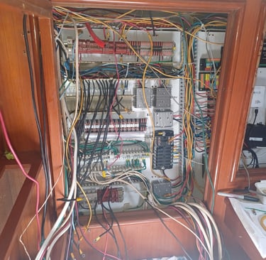
16 May
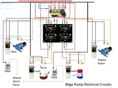
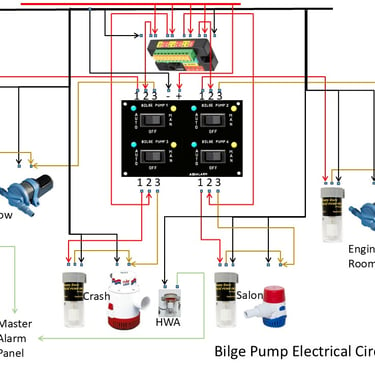
In order for the Yacht Devices Run Time model to monitor the bilge and fresh water pumps, it is expecting the NEG side of the circuit to run through it. This is the reason I was hesitating on hooking up all of the DC negatives. I have since realized that we are likely running new wires to the 3 pumps in question, so I went ahead and just tied in all of the DC grounds today. We will worry about the 3 pumps when we run new wire to support them.
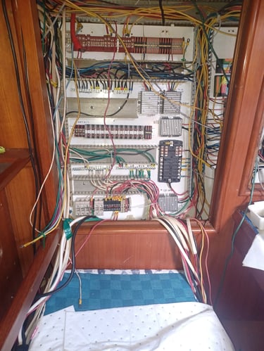
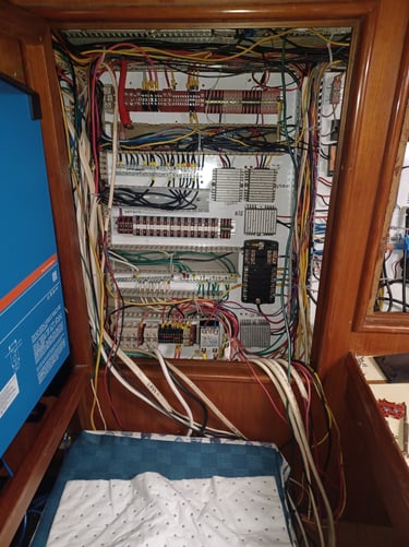
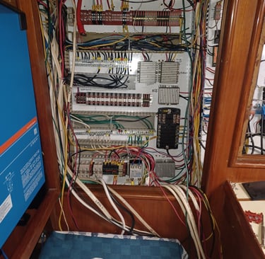
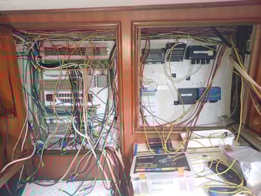
29 May - finished running the new wire supporting the planned circuits and spent 5 hours terminating everything in the electrical panel area including the majority of the non-Victron related master alarm panel circuits.
2 Jul - Batteries arrive
Write your text here...