Plumbing
Plumbing Refit Plan
Water maker -
The original watermaker is a continuous duty 1.5 gal/hr unit.
We are going to replace it with our Seawater Pro system with a new control panel faceplate and a new high pressure pump/motor.
Fresh Water pump
Upgrade to a 24VDC pump
In order to free up valuable space in the engine compartment, relocate to under the AFT Berth along with the accumulator tank.
Hot Water Heater (110VAC)
In order to free up valuable space in the engine compartment, relocate to the cabinet on the Starboard side of the AFT Berth bed
Bilge pumps
Replace with 24VDC pumps
Add a high volume crash pump
Add high water alarms for use on the master alarm panel.
Shower pumps
Replace with 24VDC pumps
Washdown saltwater pumps
Anchor washdown - replace with 24VDC pump
Stern Washdown - add a new 24VDC pump and plumbing
Fresh Water Tanks - Inspect/ Treat
Reconfigure to be 2 linked starboard and port, convert the 5th one to diesel
Add 2 Senders for use on the AlbaCombi to get onto the NMEA 2000 backbone
Fuel Tanks - Inspect/ Clean
Convert 1 water to diesel
Reconfigure to be 2 tanks (starboard, port) with both tanks on each side plumbed as one
Add 2 tank senders (P/SB) and tie into AlbaCombi
Black Water System - verify operation
Replace pumps with 24VDC
Replumb/ Install Hot water tank when new engine is installed
Address any leaks
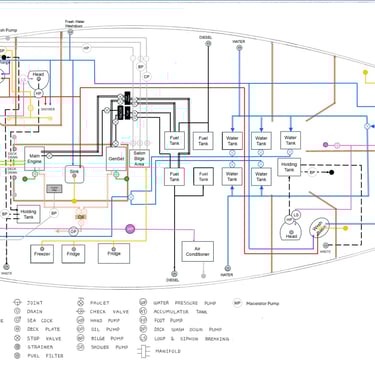
We have updated the image below to reflect the above changes.
Oct 2025 - the below pic has been updated yet again as we have made more decisions to simplify the system.
Plumbing changes
The plumbing on the boat was in pretty good shape compared with most of the remaining systems
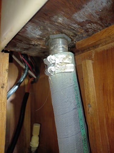
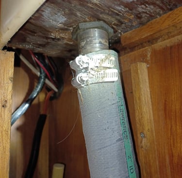
We were aware of some leaks around the hot water heater and the accumulator as well as many of the thru hulls hadn't been exercised in quite some time and where likely frozen in place.
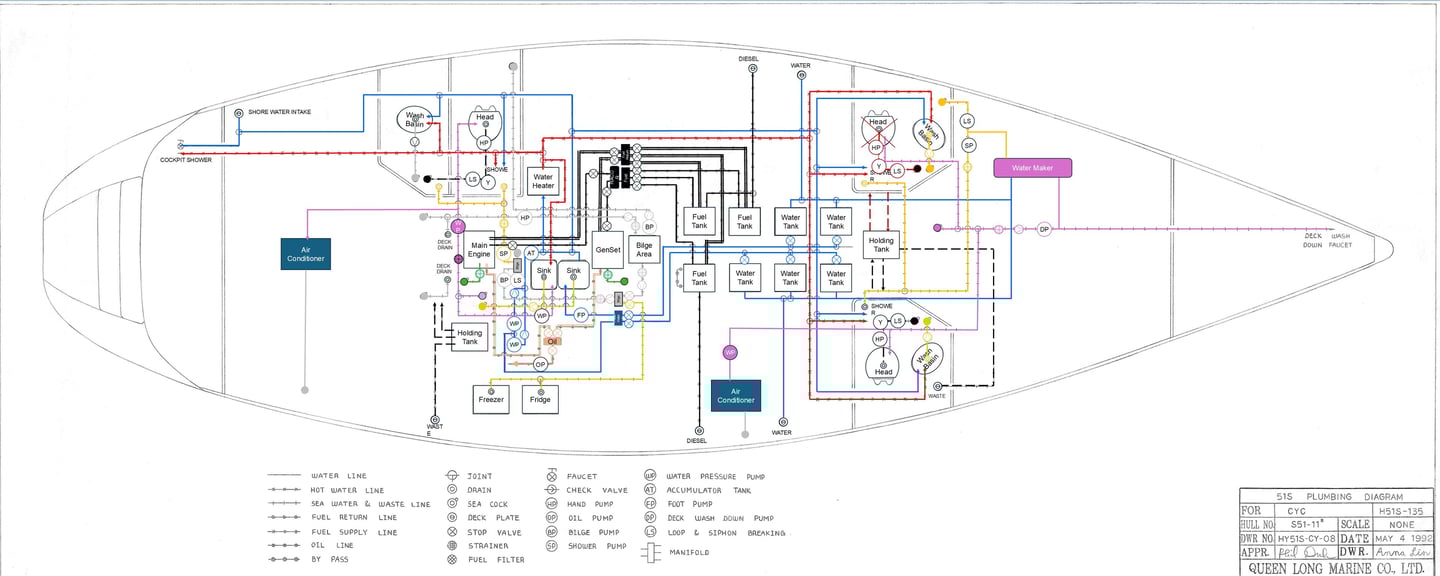
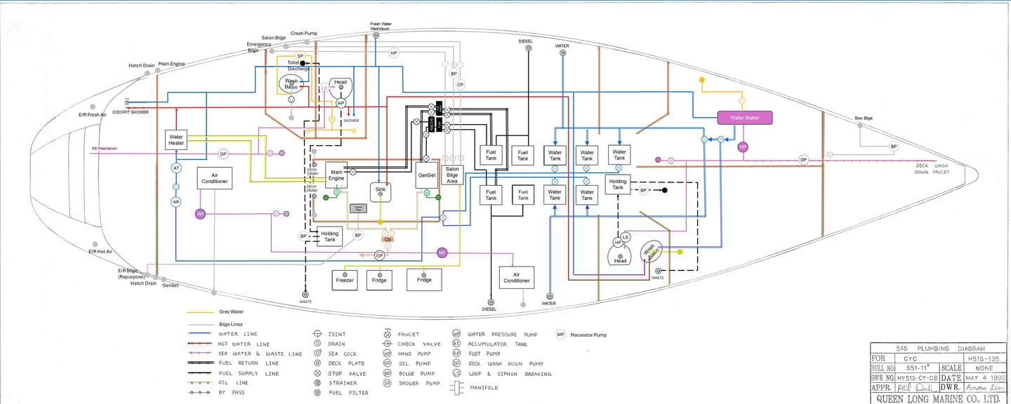
The picture below is a colorized image of the plumbing diagram we received from the original builders. The received image is likely not for our specific model, but it is close enough for us to work with. We noticed the water tank configuration was different, and the diagram did not include the necessary feed and exhaust lines for the air conditioners.
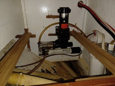
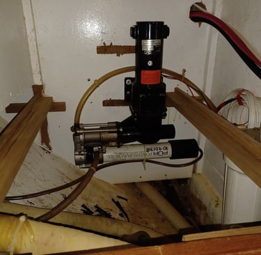
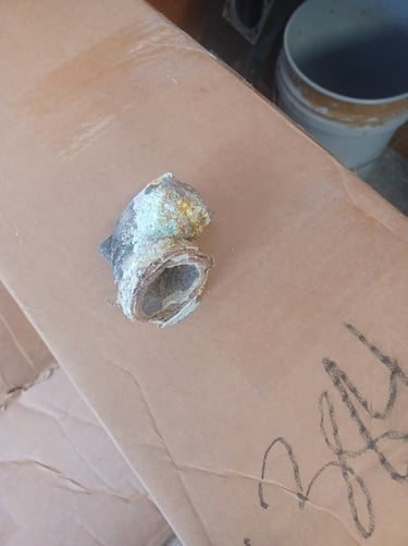
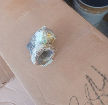
We also found a water maker that was not depicted on the diagram. Picture to the right.
Finally one of the previous owners removed the toilet in the 3rd head when he converted it to be his workroom.
15 May
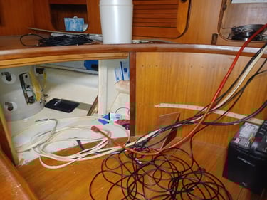
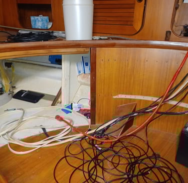
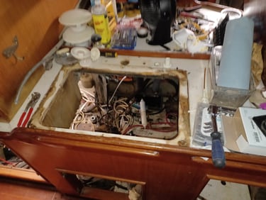
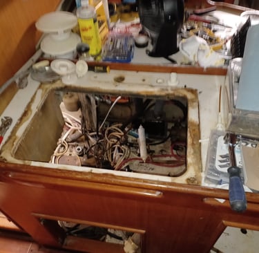
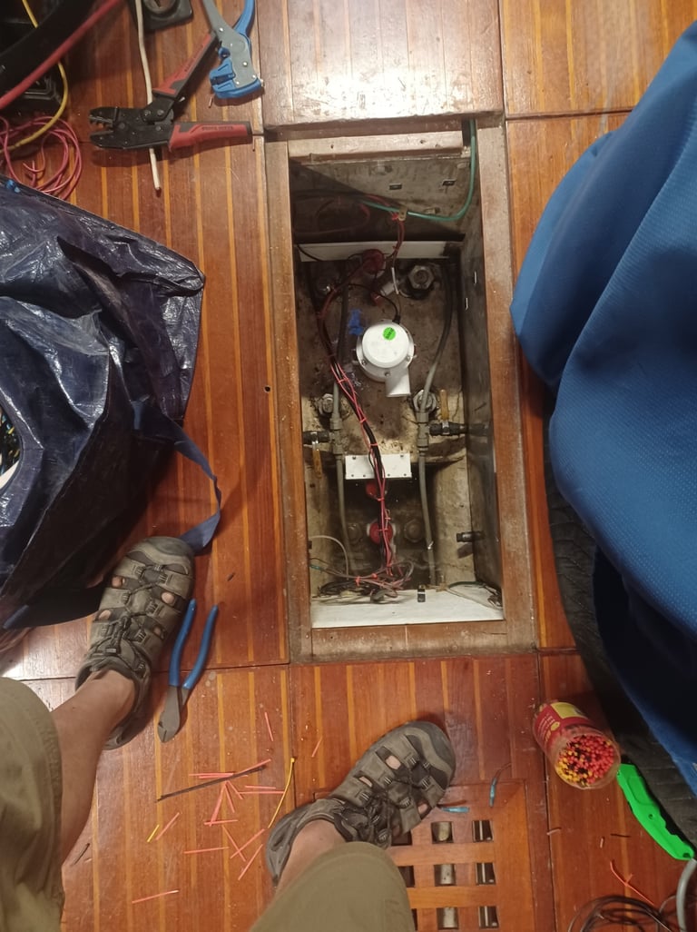
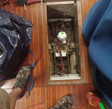
The engine bay plumbing has been disassembled - it matches the diagram
We are considering consolidating the main engine and the GenSet raw water intake to a single thru hull with a single new strainer that then can feed both motors. The issue we are trying to solve is to have a shutoff valve that is easily accessible as well as a strainer location that is easily accessible. The existing thru hulls are under a substantial amount of plumbing related to the motors and bilges (there are 3 thru hulls on either side of the engine bay that run just outside the center line stringers. Because of the amount of hoses in the area, none of the thru hull valve handles are easily manipulated and most required a breaker bar to get them to move. The existing strainers were older style that made them difficult to clean without dumping lots of sea water into the engine bay and potentially onto the motors themselves.
The Bilge plumbing is also disassembled - we found 2 remote pumps in the Engine bay and one submersible in the bilge. The plan is to go with a remote pump for the engine bay bilge which we plan to physically "dam" to separate it from the main bilge. The main bilge will get 2 submersible pumps - 1 will be the primary pump and the second will be the boat crash pump. The high water alarm in the salon bilge will also activate the crash pump.
The plumbing in the area under the port forward berth sole is a mess of abandoned hoses and unused thru hulls. Right now the plan is to remove and patch all of the thru hulls related to the port head (3), patch the hole where the sonar was located and reuse the depth transducer hole for the water maker discharge. The remaining thru hulls are for the water maker, salon AC and anchor wash intake (all 3 share the same thru hull) and the toilet black water discharge.
The plan is still to go forward with replumbing the aft most fresh water tank to diesel and then tying the port and starboard side diesel tanks together to make 2 tanks (P & S) and then do the same with the fresh water tanks. We will install senders into the deepest of the 2 diesel and 2 fresh water tanks so that their level can be monitored.
25 May
Hot Water Heater placed in its new home
New 110VAC circuit run to the new location for the hot water heater
Oct 2025
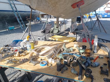
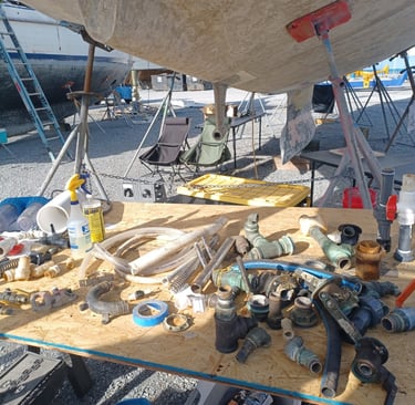
We have evolved a bit. All of the pumps needed are now purchased. We have knocked all but 1 of the old thru hulls out and most of the holes are glassed over. We have purchased new ForSpar composite thru hulls to put back in once the hull is ready. Many of the original brass thru hulls were no longer bonded to the boat bonding system and therefore where well into Galvanic Corrosion. At least 3 fittings crumbled in my hands. So we made the decision to remove and replace everything. Several of the old thru hulls were likely still serviceable, but with the ForSpar thru hulls, corrosion is no longer an issue.
We have Pex A for the fresh water system. There are still a few more fittings needed to rebuild it. We have also replaced almost all of the original bilge, sanitation and raw water hoses.
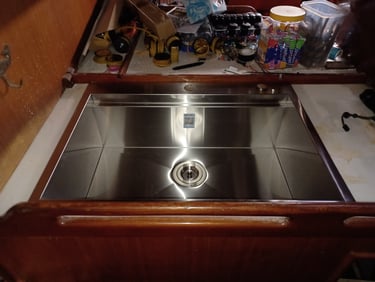
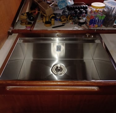
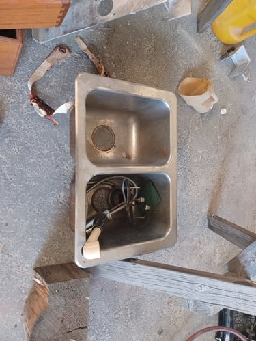
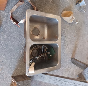
We also decided that the old double basin sink was not what we wanted going forward so it has also been replaced. We had to cut the hole slightly larger. In the process, we discovered that the drains in the old sink were leaking causing further water damage.
All of this has resulted in us permanently glassing over several thru hulls, re-architecting the black water system, properly decomissioning the forward port head, removing the shower plumbing from the forward starboard head, re-architecting the master shower and also modifying the locations of several thru hulls. All of these changes should result in a much simpler plumbing environment with mostly new hoses and all new thru hulls.
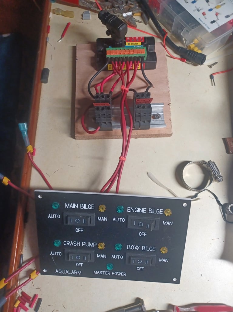
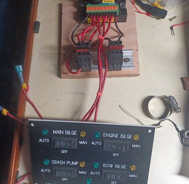
The bilge pump system is also getting a major re-architecture with the addition of a new bow bilge (given the water tight bulkhead) a new engine room bilge (we have split the bilge at the engine room to contain any spills) and a new 4000 GPH crash pump. Finally we got a new control panel made up.
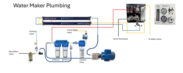
Water Maker
Our water maker has been a bit of a struggle. We have had some issues related to old parts and lack of understanding, but we are going to start fresh with this boat. We have the vessels, filters. The old high pressure pump was leaking so we left it and the old motor behind.
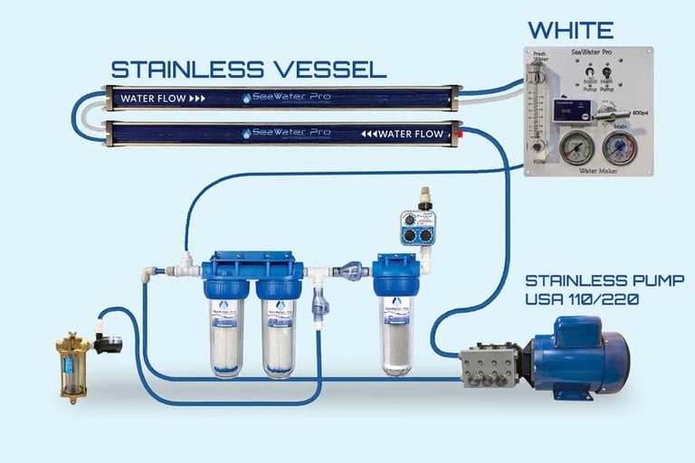
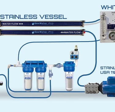
The image to the right is the basics of how the system is configured. We are discussing with Sea Water Pro on being a beta tester for a first generation automated system where there will be a new automated control system so that the we no longer need to mind the pressure regulator and various valves. Much more to follow but there are exciting changes coming to how we make fresh water.
The basic system is depicted at the right. The sea water enters the system at the lower left and is plumbed up to the 2 stage particulate filter. The water that exits the filter is then ingested into the High pressure pump. The water leaving the pump and in inlet sides of the 2 reverse osmosis membranes is pressurized to 800 PSI. The fresh water molecules are forced through the membranes and onto the product side. From there they pass through a flow meter and pressure gage and then into our tanks. There is a diverter to test water prior to committing it to our tanks. The high pressure side continues to the pressure regulator and then on the other side of membranes the waste brine water is sent overboard.
The control panel allows us to monitor Total Dissolved Salts (TDS - Water quality), input pressure and output pressure as well as product water flow rate. This system is capable of 40 gallons per hour and takes about a kilowatt of power to produce 40 gals.
There is also plumbing in the system to allow us to backflush the system after a water making session. On the back flush leg, there is an additional carbon filter to prevent any chemicals that may be present in our tanks from getting to and damaging the RO Membranes. This may happen if we need to treat our tanks, or we use a land based water source to fill our tanks.
This system is likely to least energy efficient system on the market, but that is opposed by the simplicity of the system. There are only 3 moving components - lift pump, high pressure pump and the pressure regulator. More efficient systems have a pressure recovery vessel and we have read lots of feedback about the long term reliability and cost to maintain that part of those more efficient system. In the big scheme of things, we produce about 15 KW of power daily and we plan to make water every 2-3 days. We can afford a kilowatt of energy for simplicity.
This system will be installed under one of the forward berths with the membranes mounted an the centerline bulkhead between the berths. The pump will be installed nearby.